How to learn Learning Verilog ?

Learning Verilog itself is not a difficult task, but creating a good design can be. But we focus on simple designs here and I will try my best to explain things as simple as possible.

If you had been programming with procedural languages such as C, C++, you will have to make up your mind to understand that not all things happen sequentially in the digital world. A lot of things happen parallel too. When I started learning Verilog, I used to write code sequentially as if I was writing a C program. C programs are running on microprocessors, which execute one instruction at a time sequentially. So it is easy to write a program in a way how you want things to happen one step at a time.

And if you look closely, this is the weak point of microprocessors / microcontrollers.

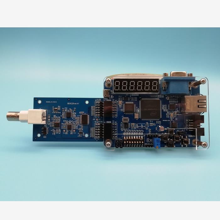
You need a fpga board to study verilog

They can do only one thing at a time, one and only one thing (of course I’m talking about single core devices!). But unlike microprocessors, digital circuits (FPGAs, CPLDs, and ASICs) can do many things at the same time. And you need to learn how to visualize many things happening at the same time in contrast to many things happening at different times, one thing at a time, in a procedural language.

Verilog Modules

A Verilog module is a design unit similar to a black-box, with a specific purpose as engineered by the RTL designer. It has inputs, outputs and it functions as per its intended design. A simplest Verilog module could be a simple NOT gate, as shown in the second image below, whose sole job is to invert the incoming input signal. There is no upper bound on the complexity of the Verilog modules, they can even describe complete processor cores! Verilog deals with digital circuits.

In Verilog realm, modules can be considered as equivalent to components in a digital circuit, as simple as a gate or a complex entity like ALU, counter, etc… Modules are analogous to classes in C++ in a way that it is self-contained and give a finite number of methods (ports) to interact with the external world.

Modules can be instantiated like classes are instantiated in C++ too. But beware; modules are not 100% similar to classes when it is implemented. For easy understanding, a module can be simply represented graphically as a box with a number of ports.

The ports can be inputs, outputs or bidirectional. Ports can be single bit or multiple bits in width. The image below represents a module with a few inputs and outputs. The number of inputs and outputs, their width and direction will depend solely on the functionality of the module.

Fundamentally Verilog (or most HDLs for that matter) is all about creating modules, interconnecting them and managing the timing of interactions.

Enough talk, we didn’t even write a “Hello World” program yet. So how do we get our hands dirty with Verilog? Let us design a NOT gate in Verilog, simulate it and test it in real hardware. A NOT gate (a.k.a an inverter) would be the simplest of all gates. The output of an inverter is always the negation of the input. ie; B = !A, where A is the input and B is the output. Below table summarize the behavior of NOT gate as a truth table.


What is RTL and Verilog ?

What is RTL?

RTL stands for Register Transfer Level. You might also encounter the terms Register Transfer Logic or Register Transfer Language, they all mean the same in the context of hardware designing. RTL is a higher level abstraction for your digital hardware design and comes somewhere between strictly behavioral modeling on one end and purely gate-level structural modeling on other ends.

Behavioral modeling is explained in the next articles in this series so don’t be daunted with this term. Gate modeling means describing hardware using basic gates which is quite tedious. RTL can also be thought of as analogous to the term “pseudo-code” used in software programming. It is possible to describe the hardware design as sequences of steps (or flow) of data from one set of registers to next at each clock cycle.

Therefore, RTL is also commonly referred to as “dataflow” design. Once the RTL design is ready, it is easier to convert it into actual HDL code using languages such as Verilog, VHDL, SystemVerilog or any other hardware description language. HDL and Verilog are explained in the next section. Check out the Wikipedia page on RTL for more information (https://en.wikipedia.org/wiki/Register-transfer_level)

What is Verilog?

In the previous paragraphs, I mentioned the word “oversimplified” two times. The reason is that FPGAs are much much more than just a bunch of gates. While it is possible to build logic circuits of any complexity simply by arranging and connecting logic gates, it is just not practical and efficient. So we need a way to express the logic in some easy to use format that can be converted to an array of gates eventually.

Two popular ways to accomplish this are schematic entry and HDLs (Hardware Description Language). Before HDLs were popular, engineers used to design everything with schematics. Schematics are wonderfully easy for small designs but are painfully unmanageable for a large design (think about Intel engineers drawing schematics for Pentium, which has millions of gates! it is unacceptably complex).

If you have some electronics background, your initial tendency will be to use schematics to realize your design instead of learning a new language (This happened to me, honestly). For the aforementioned reasons, we will stick with HDL throughout this tutorial.

Verilog is a Hardware Description Language (HDL) which can be used to describe digital circuits in a textual manner. We will write our design for FPGA using Verilog (as if you write microcontroller programs in C and Assembly). Learning Verilog is not that hard if you have some programming background. VHDL is also another popular HDL used in the industry extensively.

Verilog and VHDL share more or less same market popularity, but I chose Verilog since it is easy to learn and its syntactical similarity to C language. Once you are comfortable with Verilog, it should be easy learning VHDL as well. Want to read more about Verilog? Check out this wiki page (http://en.wikipedia.org/wiki/Verilog) or check this tutorial (http://www.asic-world.com/verilog/index.html).

What tools do we need?

1. A good text editor (I use Notepad++ )

2. Xilinx ISE Webpack (Download from Xilinx for free. Registration required).

FPGA Beginner Boards

3. A good FPGA development board (Mimas V2 FPGA Development Board is used in the examples here. Picture of Mimas V2 is shown at the top of this page. If you have an Elbert V2 Spartan 3A FPGA board, that should work perfectly too. There are some differences when setting up the project for Mimas V2 vs Elbert V2 but I will point them out when it is necessary.)

4. Mimas V2 or Elbert V2 Configuration downloader software (Required only if Mimas V2 /Elbert V2 FPGA Development Board is used. Download from the respective product pages)

Additional tools may be necessary to follow advanced topics in this series. Information about such tools will be shared ass they are needed.